ADC16
16-channel 18-bit 2-MSPS ADC Module for Annotator Pro
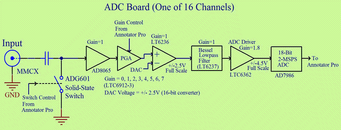
ADC16 is an analog input module for the Annotator Pro that provides 16 channels of analog to digital conversion, with up to 2 MSPS on each channel. A block diagram for a single channel is shown below.

Input: The board can be DC-coupled at the input by replacing the AC-coupling capacitor with a zero-ohm resistor; For unity PGA gain the full-scale input to the ADC board is ±2.5V; Configuration options can be made per channel at build time
DC Restore: An ADG601 solid-state switch at the input of each channel allows for a precision timed DC restore; The AD8065 op-amp has a very high input impedance that allows the AC coupling capacitor to hold whatever voltage is stored on it by the switch; Switch timing and pulse width are controlled by the FPGA on the Annotator Pro and are common to all channels
Global Gain: Global gain is the same for all channels, and is set by an LTC6910 PGA on each channel; The default PGA is the LTC6910-3 (gain options of 0, 1, 2, 3, 4, 5, 6, or 7); Alternative gain options are the LTC6910-1 (gain options of 0, 1, 2, 5, 10, 20, 50, 100) and LTC6910-2 (gain options of 0, 1, 2, 4, 8, 16, 32, 64)
DC Shift: The DC shift function is implemented using an LT6236 so that the DC level may be shifted up or down; The amount of DC shift is set by a programmable 16-bit DAC that is common across all channels. The DAC can be set to generate any shift between -2.5V and +2.5V
Filtering: The anti-alias lowpass filter prior to the ADC is a 5th order Bessel filter with -3 dB cutoff at 188.5 KHz (the cutoff frequency can be changed if needed); A digital filter can be applied in the FPGA after sampling. The digital filter response can be designed to cancel the rolloff of the Bessel filter, giving a net response that is flat in the passband.
Interface: ADC16 can be installed on the Annotator Pro at either P14/P15 or P16/P17
Dimensions: 152 x 70 mm (6” x 2.77”)
Part Number: ADC16

